TS-590S measurements - ALC Overshoot, PAR, MDS and IP3
In January 2012 I bought a new Kenwood TS-590S TRX. It’s quite a nice radio with great features such as the really good RX, a USB port for CAT with an integrated USB soundcard and a small and light-weight case.
Power Spike
After I had used it a while in contests and hunting some DX, I observed the same problem with the TX which was reported by some other hams on eham.net and other websites. There is a power spike at the beginning of each transmission, which causes my Acom 2000A amplifier to go in protection mode. First of all I checked the kenwood website if that is a known issue. Kenwood state that this problem should be solved with the TS-590S firmware version 1.02. I checked the actual version on my TS-590S and to my surprise it was version 1.05. The latest version is 1.06, so I upgraded it to see if the power spike was still present. Upgrading the firmware on the TS-590S is quite easy and after some minutes everything was done. But … the power spike was still there.
I contacted Maik DJ2QV who owns a TS-590S too. He’s an RF engineer working for a well-known measuring instruments company in Munich. As he has an old amplifier which does not have a quick-response protection he hasn’t seen that power spike, but he was complaining about a lower average output power in SSB compared to his old TS-850. We both talked to Matthias DK4YJ, also an RF engineer working for the same company as Maik. With a pile of measuring devices they made some measurements on the TS-590S. At first RX measurements were carried out. Please see below for details. Afterwards the TX measurements were made.
ALC Overshoot
The TS-590S with proper settings according to the instruction manual has a power spike which lasts for about 5 milliseconds and is two times the output power which is set via menu. Image 1 shows this measurement of the TS-590S made with a Rohde & Schwarz RTO oscilloscope. The voltage spike here is about 1.3 times the upper level. As power is a quadratic function of the voltage, the power spike is two times of the nominal output power. So if you set the TS-590S to 100 watts output, the spike will be 200 watts. This is caused by the ALC which is not able to control the output power for the first 5 milliseconds of each transmission.
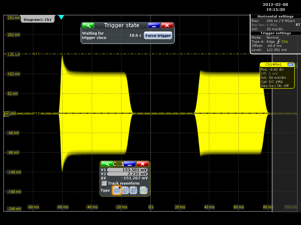 power spike caused by ALC overshoot
Together with Simon DJ4MZ, another RF engineer from Munich, we checked the service manual and wiring diagrams of the TS-590S. Matthias had doubts about one RC element with a wrong time constant in the ALC control loop. So we changed the capacitance, but nothing really happened. As we don’t think that there are other elements which can cause a buggy time response of the ALC, we assume that this is a software related bug.
ALC Reference
In the service menu of the TS-590S the ALC reference voltage can be set. This is done in the factory. We checked what happens, if this ALC reference is changed. In the internet some guys were complaining about a low average output power in SSB. They say setting the ALC reference from something about 120 to 225 will result in a better peak-to-average ratio (PAR) which means the average output power is higher. Please do not do that.
The only thing which is increased is the power spike. Matthias and Maik were able to measure a spike of four times the nominal output power by setting the ALC reference to 225. Matthias and I verified that on a second measurement on a different TS-590S. Image 2 shows the voltage peak which is about 2 times the upper level. Again, power is a quadratic function of the voltage, so the spike will be 400 watts if the TS-590S is set 100 watts.
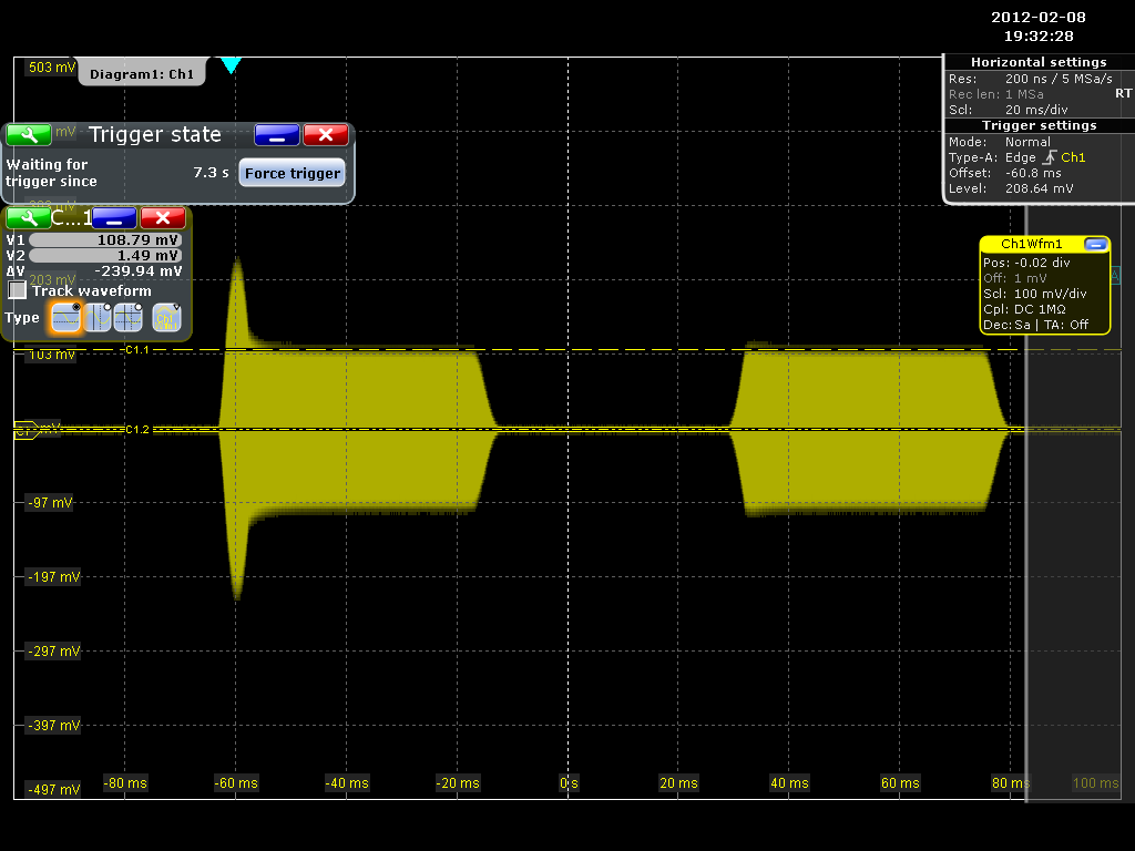 power spike with ALC reference set to 225
Workaround
In my TS-590S the ALC reference was set to 122. By reducing the ALC reference from 122 to 113 we were able to make the power spike disappear. Reducing the ALC reference level let the ALC control work all the time, also if no output is present and right from the beginning of each transmission. This is not really how an ALC should work, but at least the power spike disappears and we haven’t seen any harm so far. The only thing we oberserve is an ALC readout on the meter also when there’s no output.
Please note: Kenwood has a solution for the power spike and offers a hardware modification! Please contact your local Kenwood agency or authorized dealer. More information can be found here and here.
Peak-to-Average Output (PAR)
As mentioned before, some hams complained about a low average output power in SSB. Changing the ALC reference slightly in the service menu does not affect the ratio. When you set it to 225 the peak-to-average ratio gets worse, because you get huge unwanted peaks with every single spoken word while the average power stays the same. Some people say the speech compressor does not work properly, but we think everything works the way it should. With a setup built up by Matthias DK4YJ in his home lab we measured the PAR on the TS-590S. Image 3 shows the set-up. QRG of the TRX was 14.203 MHz and the QRG of the LO was 14.202 MHz.
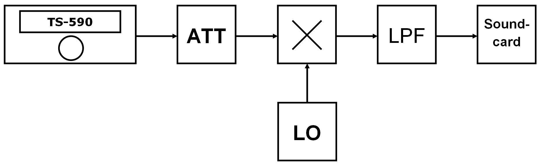 PAR measurement setup
A Python script on the PC analyzes the signal. Matthias made some PAR measurements on his IC-765 earlier. With a really aggressive contest modulation he was able to get a ratio of -4.6 dB. The power peaks 100 watts while the average is about 35 watts (-4.6 dB). This is a quite high PAR. A ratio of about -6 dB is known to be adequate, also for contests or in DX pile-ups. On my TS-590S we measured a ratio of about -7 dB, which means an average of about 20 watts while the TS-590S is set to 100 watts output power. I’m really fine with that. Perhaps it could be increased with other settings in the ALC control or speech processor of the TS-590S firmware, but I think this is nothing to complain about. A very low PAR (or high compression rate) does not implicitly mean your intelligibility gets any better. For detailed information please read the RadCom article Improving the intelligibility of SSB transmissions of Martin G8JNJ, published February 2009.
Minimum Detectable Signal and Intermodulation-free Dynamic Range
Matthias DK4YJ and Maik DJ2QV made also some RX measurements in the RF lab. To put it in a nutshell, it’s a great RX! See measurement results below.
MDS
Band   Bandwidth  Preamp   MDS
MHz           Hz           dBm
------------------------------
14 MHz       500     OFF  -129
14 MHz       500      ON  -137
14 MHz      2500     OFF  -125
14 MHz      2500      ON  -133

28 MHz       500     OFF  -134
28 MHz       500      ON  -141
28 MHz      2500     OFF  -130
28 MHz      2500      ON  -139
IP3 & IMDR3
Band   Bandwidth   Preamp  Distance     MDS    Power*     IP3    IMDR3
MHz           Hz                kHz     dBm      dBm      dBm       dB
----------------------------------------------------------------------
28 MHz       500      OFF        20    -134      -33     17.5      101 **
28 MHz       500      OFF        15    -134      -34     16.0      100
28 MHz       500      OFF        10    -134      -39      8.5       95
28 MHz       500      OFF         8    -134      -42      4.0       92
28 MHz       500      OFF         6    -134      -45     -0.5       89
28 MHz       500      OFF         4    -134      -49     -6.5       85
28 MHz       500      OFF         3    -134      -54    -14.0       80
28 MHz       500      OFF         2    -134      -57    -18.5       77
28 MHz       500       ON        20    -141      -48     -1.5       93

Band   Bandwidth   Preamp  Distance     MDS    Power*     IP3    IMDR3
MHz           Hz                kHz     dBm      dBm      dBm       dB
----------------------------------------------------------------------
14 MHz       500      OFF        20    -129      -22     31.5      107
14 MHz       500      OFF        10    -129      -22     31.5      107
14 MHz       500      OFF         6    -129      -23     30.0      106
14 MHz       500      OFF         4    -129      -27     24.0      102
14 MHz       500      OFF         3    -129      -34     13.5       95
14 MHz       500      OFF         2    -129      -38      7.5       91 **
14 MHz       500       ON        20    -137      -36     14.5      101
14 MHz       500       ON         2    -137      -50     -6.5       87
Comparison of the down-conversion RX and the up-conversion RX:
Band   Bandwidth   Preamp  Distance     MDS    Power*     IP3    IMDR3
MHz           Hz                kHz     dBm      dBm      dBm       dB
----------------------------------------------------------------------
14 MHz      2700      OFF        20    -124      -21     30.5      103 (down)
14 MHz      2800      OFF        20    -130      -30     20.0      100 (up)
6m measurements:
Band   Bandwidth   Preamp  Distance     MDS    Power*     IP3    IMDR3
MHz           Hz                kHz     dBm      dBm      dBm       dB
----------------------------------------------------------------------
50 MHz       500       ON        20    -142      -51     -5.5       91
50 MHz       500      OFF        20    -132      -41      4.5       91
* Power of the two tones
** Nearly the same results as on Rob Sherwoods NC0B Receiver Test Data website.
I’d like to say thank you to Matthias DK4YJ, Simon DJ4MZ and Maik DJ2QV for measurements, discussions and suggestions. If you have any questions please feel free to contact me.
More information about the TS-590S (reviews, documentation, software, applications) can be found on G3NRW’s TS-590 Resource Page.